

Shoring
The process of supporting a building, structure, or trench with shores (temporary buttresses) when in danger of collapse or during repairs or alterations or for the excavation as required for new structures. Shoring is typically a timber or metal prop. Shoring may be vertical, angled, or horizontal. Raking Shores consist of one or more timbers/buttresses sloping between the face of the structure to be supported and the ground. Other shoring methods could include hydraulic shoring, soil nailing, beam and plate, and vertical shoring.


Purchase your Shoring Equipment from us.
TOWER OVER 60'-0 HIGH
ALLOWABLE WORKING LOADS (LBS./LEG)
- Use 4146 loading as above for combinations of 4144, 4145, 4146, 4124, 4125, and 4126 frames used in one tower
- Total screw jack adjustment is the sum of the adjustment Top & Bottom = A + B
- The above allowable leg loads reflect a 2.5:1 safety factor
- Reduce the above allowable loads 10% when using 02xx-12, 13 or 15 cross braces (special application).
- Reduce the above allowable loads 20% when using
0215-07 Straddle in one level of a tower - no reduction necessary for 0215-10 straddle braces (special application)
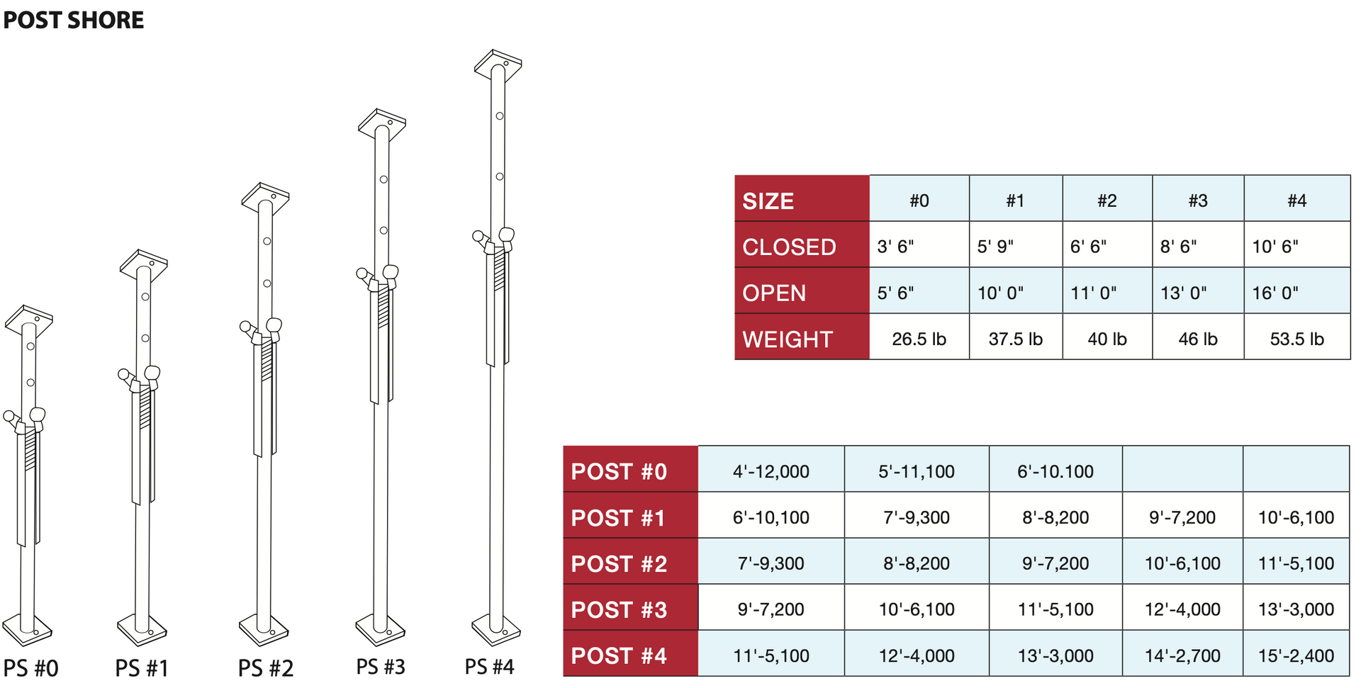
SHORING POST Note:
The extensions in the above table are based upon details given in C.S.A Standard S269,1-1975. Falsework for construction purposes and details of actual extension dimensions can be supplied upon request F.O.S 3:1
The heavy duty collar is made from malleable 78,400 lb (35,556 kg) cast iron to withstand high impact shock loads and incorporates the following features:
- A self cleaning device which automatically clears the threads of debris as it rotates, thus assuring quick and easy adjustment.
- 2' (51 mm) of full depth thread.
- A strong 3/4" (19mm) forged handle that rotates fully for easy use and compact storage.
- A holed boss for inserting podger bar for extra leverage in confined spaces
On site shors are set with 3 basic actions:
- Position inner tube to closest possible height of slab
(pin holes at 5 1/2" (140 mm) centers). - Insert captive pin fully through holes and slots above the nut.
- Adjust final proping height by turning shore nut to raise or lower as required.